
Ghosts of Pattullo: Temporary Works in Bridge Construction – Tower Crossbeam Falsework Part A
- Raj Singh

- Feb 17
- 4 min read
This article in the Ghosts of Pattullo series explores temporary works in bridge construction through the design and staged verification of the ULMA falsework system used to construct the tower crossbeams.

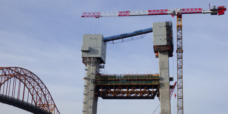
The 160-metre tower of the new Pattullo Bridge’s cable-stayed main span—now known as the stal̕əw̓asəm (Riverview) Bridge—is configured as an H-shaped pylon, with two legs each supporting a vertical plane of stay cables. The tower legs rise from the pile cap inclined toward one another. At approximately 60 metres above deck level, they straighten to become vertical, creating the geometry required to house the stay cable anchorages. Connecting these legs are two substantial transverse post-tensioned concrete crossbeams.
The Lower Crossbeam (LCB), positioned at approximately +39.00 m elevation—about 30 metres above the pile cap and beneath the superstructure—ties the inclined legs together while also supporting the deck framing above. The Upper Crossbeam (UCB), located at approximately +107.00 m elevation—roughly 60 metres above deck level—connects the legs at the geometric deviation from inclined to vertical. In addition to acting as a compression strut, it prevents differential movement between the tower legs at the critical cable anchorage zone.
The lower crossbeam measures approximately 31 metres in length, 7.0 metres in width, and 5.5 metres in depth. The upper crossbeam spans approximately 28 metres, with a width of 5.5 metres and a depth of 6.5 metres. Both are hollow reinforced concrete box sections with average wall thicknesses of approximately 600 millimetres. The resulting concrete volumes place the self-weight of each beam in the range of 1,100 to 1,200 tonnes—roughly equivalent to 750 passenger cars suspended between tower legs at elevations exceeding 100 metres.
Casting structural elements of this magnitude between inclined pylons introduces a fundamental construction challenge. The temporary support system must resist gravity, lateral concrete pressure, wind at elevation, and construction live loads—while transferring these demands into the permanent tower walls without overstressing the structure during its most vulnerable phase.
The ULMA Falsework System
To enable staged casting of both crossbeams, ULMA’s Heavy Duty MK Truss system was configured as the primary falsework spanning between the tower legs.

The system is modular, based on Warren-type truss geometry formed by MK-120 walers and bolted junction nodes creating repeating triangular units. For the Pattullo application, a double-stacked truss configuration was used to achieve an overall depth of approximately 5.5 metres, significantly increasing flexural capacity while maintaining modular efficiency. Two double-stacked truss planes were interconnected with horizontal and diagonal bracing to form a single stable unit. Six such units (12 truss planes) spanned between the tower legs to create the complete support assembly. This 400-tonne steel falsework structure supported the ENKOFORM HMK formwork and fresh concrete during casting of the lower crossbeam. After completion and curing, the system was dismantled and reassembled at the upper crossbeam elevation.
Spannovation was engaged to provide a full independent structural verification of the ULMA falsework system in accordance with the Canadian Highway Bridge Design Code and to assume professional responsibility for its design. The engineering scope extended beyond member capacity checks. It required confirmation of global stability, wind performance at elevation, staged load transfer into the permanent tower walls, and compatibility of all interface components including gantry brackets, jacking assemblies, and bearings.
Verifying the Falsework: 3D Staged Analysis
The falsework system's behaviour evolved with the concrete pour stages, and the analysis had to reflect that evolution. A full three-dimensional staged construction model was developed with loading stages applied to mirror the actual casting sequence. The concrete was cast in stages rather than in a single monolithic pour, allowing the hardened first-stage concrete to participate structurally in resisting subsequent loads. The temporary works were therefore analysed not as an isolated steel structure, but as an interacting system coupled with a progressively stiffening concrete element.
During the first stage, the bottom slab and exterior wall formwork were erected together. Fresh concrete self-weight, construction live loads, and wind acted directly on the exposed truss and formwork assembly. Lateral concrete pressures were calibrated based on pour rate and wall geometry, with design checks performed for pressures between 40 and 60 kPa. The analysis focused not only on total concrete weight but on pressure effects governing walers, tie rods, and truss demand during active placement.

Once the bottom slab hardened, the structural behaviour changed measurably. The stiffened slab began transferring load directly into the tower walls, reducing wind demand on the truss system. This shift in load path was explicitly captured in the staged model. After the second stage cured, the partially completed crossbeam contributed further stiffness, allowing the final pour to be supported by both the falsework and the hardened concrete.
The truss itself was modelled member-by-member using true panel-point geometry rather than simplified beam idealizations. MK-120 profiles—paired perforated UPN sections—were checked using their actual sectional properties. Tie rods were verified at service limit state in accordance with manufacturer tables. Interface components, including gantry brackets, jacking anchorages, bearings, and connection assemblies, were incorporated to ensure realistic stiffness compatibility and load transfer into the permanent structure.
As an additional verification, a deliberately conservative scenario was analysed assuming the combined wet concrete weight from multiple stages acting simultaneously. Even under this severe assumption, primary truss members demonstrated adequate capacity. The purpose of this exercise was not to design for an unrealistic condition, but to demonstrate robustness of the system.
The outcome was not simply a check of capacity, but a rigorous validation of behaviour—capturing gravity, concrete pressure, wind, thermal effects, staged construction sequencing, evolving stiffness, and shifting load paths—at elevations where tolerances were tight and consequences significant.


Comments