Incremental Launching of Steel Bridge Girders #4: The Launch Bed
- Raj Singh

- Aug 9, 2024
- 3 min read
The launch bed is crucial in the incremental launching process. Located behind the abutment, it serves as the staging area where the steel girder segments are assembled before being launched across the bridge piers. It supports the loads of the steel girders during both assembly and movement.
Typically, the launch bed consists of compacted soil to support the loads transferred from temporary supports resting on it. The bed often includes a system of rails or rollers to support and facilitate the movement of the girder segments during the launch. Depending on the project requirements, the launch bed can include stationary supports, moving supports, or both, to safely distribute the vertical and horizontal loads to the ground as the girders are pushed forward.
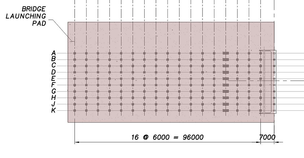
In the Athabasca project, the launch bed was a substantial space, approximately 100 meters long and 50 meters wide, designed to facilitate the assembly and accommodate the simultaneous launch of 10 girder lines. This setup required robust preparation, given the complexity and scale of the operation. The entire bed was densified to a Proctor density of 98% to provide a firm and stable sub-grade. The steel segments were assembled on the launch rails, which were H-piles oriented along each girder line with their flanges vertical. Solid wood blocking beneath the H-piles, combined with intermediate concrete footings spaced at 6-meter intervals, ensured that loads were effectively distributed to the compacted sub-grade. The H-pile segments were welded together along each girder line to provide continuity and strength.

The launch bed featured two critical support points for the girders. The first was a stationary intermediate support located 25 meters behind the abutment roller support. The second was a moving support at the tail of the girder segment, utilizing a sled assembly that could slide along rails as the girder moved forward. This configuration was used to minimize the need for multiple intermediate supports given the length of the girder assembly, which extended up to 90 meters behind the abutment in some of the launch stages. The continuous rail system, supported by concrete footings, was employed for distributing the moving load from the sled to the ground, ensuring a smooth and controlled launch.

The Sombrio project employed a different approach due to the shorter maximum girder assembly length of about 60 meters. The launch bed for this project was 65 meters long and 10 meters wide and utilized two intermediate roller support locations for each girder line, positioned at distances of 15 meters and 35 meters from the North Abutment.
The support footings, 400 mm deep and made from cast-in-place concrete, were embedded into the compacted soil of the launch bed. This provided the necessary support and lateral resistance to stabilize the structure against transverse horizontal wind loads. Unlike the Athabasca project, the Sombrio launch bed did not use a moving support at the tail. Instead, it relied on two stationary supports and did not incorporate launch rails. This configuration was more cost-effective than using the rail system similar to the Athabasca project. During the launch, the girder lines were supported on Hillman Rollers, facilitating the movement of the girders across the supports.

Conclusion
The planning and preparation of the launch bed are important aspects of the incremental launching process. Each project requires a tailored approach to the launch bed, depending on factors such as the length of the girder assembly, the number of girder lines, and the specific site conditions. As seen in the project examples, different strategies - from the use of multiple intermediate supports to the incorporation of launch rails - can be employed to ensure that the launching process is efficient and safe.


Comments