
Ghosts of Pattullo: Temporary Works in Bridge Construction – Tower Crossbeam Falsework Part B
- Saqib Khan

- Mar 24
- 3 min read
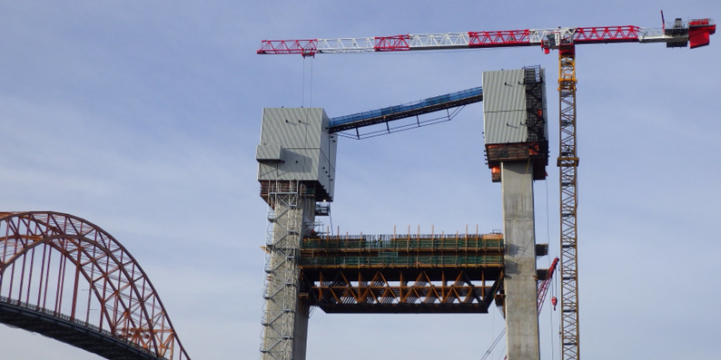
The ULMA falsework truss used to cast the lower and upper tower crossbeams introduced support reactions approaching 1,500 kN at each tower leg. These reactions included the self-weight of the falsework, staged wet concrete loads, construction live load, and wind effects at high elevations.
Temporary supports were required to resist these forces without slip and without overstressing the permanent tower. The supports had to be removable after completion of the crossbeams and prior to lowering the falsework. The solution needed to provide high shear resistance, redundancy in load path, and constructability at height while minimizing interference with the dense tower reinforcement.
The Adopted Solution: Post-Tensioned Friction Brackets
The adopted solution consisted of welded steel corbel assemblies clamped to the tower legs using high-strength 36 mm diameter post-tensioned bars. Each bar was stressed to approximately 700 kN after lock-off, generating a total clamping force slightly above 2,000 kN per bracket. This compressive force was applied across a grout bed placed between the steel base plate and the tower wall. The grout was specified at a minimum strength of 45 MPa, and the tower face was intentionally roughened to mobilize shear resistance through mechanical interlock.
Vertical shear from the falsework was resisted primarily through compressive clamping force acting across this roughened interface. The required vertical resistance represented roughly sixty percent of the available clamping force, providing margin under ultimate loading. Cohesion between steel and grout was conservatively neglected.

Redundancy in Load Path
To avoid reliance on a single load-transfer mechanism, the bracket detail included welded steel tabs beneath the base plate. These elements were evaluated independently as rigid shear keys bearing against the grout. Conservative bearing formulations demonstrated that the shear key mechanism alone provided capacity exceeding the design vertical demand. Even if the friction contribution were neglected entirely, the detail remained adequate. The bracket therefore possessed redundancy in load path rather than depending on a single interface assumption.
Verification of Local Behaviour
Beyond global shear resistance, the design verification addressed local concrete bearing stresses, compressive stresses induced by post-tensioning, and splitting resistance of the tower face. Losses in post-tensioning force were considered, and bracket stiffness was incorporated into the staged falsework model to ensure realistic support conditions.
The arrangement of post-tensioned bars was refined to reduce reinforcement conflicts and improve redundancy, responding directly to comments from the bridge designer and independent checker during technical review.

A Controlled, Removable Interface
The completed bracket system functioned as a controlled structural interface between temporary and permanent works. It transferred significant vertical and horizontal forces while avoiding permanent embedded elements, minimizing interference with tower reinforcement, and allowing complete removal and surface restoration after construction.
Once the falsework trusses were secured to the strand jack lowering system, the brackets were relieved of their vertical reaction, the PT bars were de-tensioned, and the brackets removed prior to lowering the ULMA falsework. The tower concrete surface was then restored to its intended finish.
Shear transfer was verified through clamping friction, supplemental shear key capacity, and local bearing checks. Under conservative alternate assumptions, the system remained safe and adequate. The brackets were temporary in duration but carried significant forces and fulfilled a critical supporting role. Their engineering required explicit definition of load path, validation of interface behaviour, and demonstration of redundancy.


Comments