
Ghosts of Pattullo: Controlled Lowering of the ULMA Falsework System
- Raj Singh

- Mar 31
- 4 min read
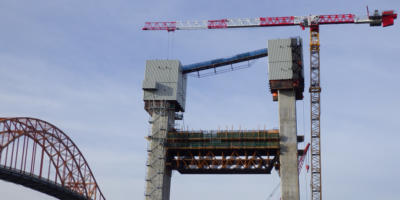
In Part A, we described the ULMA MK heavy-duty truss falsework used to cast the lower and upper tower crossbeams on the Pattullo Bridge Replacement Project—now known as the stal̕əw̓asəm (Riverview) Bridge—and how its behaviour was verified through staged 3D analysis. In Part B, we focused on the post-tensioned friction brackets that transferred reactions approaching 1,500 kN at each tower leg into the permanent structure safely and reversibly. Part C completes the sequence. The engineering challenge at this stage was to remove a 400-tonne temporary structure from elevation safely in a controlled manner.
Installation Was Modular — Removal Was Not

The falsework system comprised six modular MK truss units. During installation, each unit was crane-hoisted individually into position between the tower legs and seated onto its bearing assembly, which in turn was supported by the friction brackets. This modular approach kept individual lifts manageable, allowed geometry and seating to be confirmed unit-by-unit, and facilitated controlled assembly at elevation.
Once the crossbeam was constructed, however, removal could not simply reverse installation. The completed crossbeam above the falsework prevented lifting from above using cranes. Dismantling the system into individual units at elevation would have required extensive work-at-height exposure, repeated rigging operations due to restricted access, and intermediate stability checks under constrained access conditions. A controlled lowering strategy to remove the entire assembly was therefore adopted, using the newly constructed crossbeam as the support platform for the removal system.
That strategy was to use the newly constructed crossbeam itself as the temporary support platform for a lowering system. This enabled the entire falsework assembly; approximately 400 tonnes, to be lowered as a controlled unit, eliminating the need for multiple dismantling operations at elevation.
Converting Supported Falsework Into a Suspended Load
The first step in lowering was to transfer the full falsework reaction into the strand-jack system before releasing any of the existing tower-leg supports. Strand-jack support beams were installed to bear on the top surface of the completed crossbeam, with transverse top beams forming a temporary lifting frame above the falsework. Underslung bottom transverse beams were then connected into the strand-jack rigging to capture the truss assembly from below and convert it into a controlled suspended load.

Two lifting locations were provided along the truss length so the falsework could be supported at two points during descent. This arrangement utilized a total of four DSI TENSA 3000 LIFT strand jacks, each equipped with 12 × 15 mm high-strength strands, enabling synchronized lifting/lowering and control of span rotation throughout the operation.
The strand jacks were operated in a synchronized manner connected to a common manifold to progressively transfer the falsework weight from the tower-leg bearing assemblies and friction brackets into the strand-jack system. Only once the falsework was demonstrably captured and supported by the jacks could the tower-leg supports be released.
With the falsework load transitioned into the strand-jack system, the friction brackets were relieved of their vertical reaction, the post-tensioning bars were detensioned, and the bracket assemblies removed prior to lowering. This cleared the tower legs for the descent and restored the tower interface before the lowering operation proceeded.
Controlled Descent
Lowering a heavy falsework assembly from elevation is a structural operation with defined stability requirements. The objective was to prevent sudden movement, avoid impact loading, and maintain predictable geometry throughout the descent, including under construction-stage wind conditions. The contractor was required to monitor weather conditions and complete the lowering process under restricted wind conditions, with maximum wind speeds limited to 4.5 m/s (16.2 km/h).
For the upper crossbeam, the falsework was lowered approximately 60 metres down to the lower crossbeam level. From there, the truss units were dismantled independently using a trestle-based crane, providing a controlled dismantling environment without requiring overhead crane extraction from the tower top.
Strand jacks enabled the descent to proceed in controlled increments, with the ability to pause at defined stages while maintaining stability. The falsework was lowered while preserving clearance and alignment between the truss assembly and the tower legs, ensuring the structure remained stable and free from unintended contact or torsional response. This approach also ensured that loads during removal remained within a known load envelope through the strand jacks into the completed crossbeam.
Dismantling and Reuse
Once the falsework was lowered to a safe working elevation, the system could be dismantled and prepared for reuse. This repeatability is one of the practical advantages of the ULMA MK system: a modular falsework assembly can be assembled, used, lowered, and reconfigured in a controlled cycle rather than fabricated as a one-off structure.
The full sequence: crane installation of modular truss units, staged casting support, verification through staged analysis, and controlled lowering; was executed at the lower crossbeam elevation and then repeated at the upper crossbeam elevation. The second cycle occurred at greater height with more constrained access, reinforcing the importance of a removal strategy where crane removal was unfeasible.

Spannovation was responsible for engineering the lowering scheme, designing the associated temporary works, specifying the strand-jack system, and verifying stability of the falsework structure throughout the operation.
Once the falsework was removed, the only visible result was the permanent crossbeam itself. No embedded corbels remained, no permanent support steel was left behind, and the temporary load-transfer hardware was removed with restoration of the tower surface.


Comments